 ██████╗ ███████╗██╗██████╗ ██╗   ██╗███████╗
██╔═══██╗██╔════╝██║██╔══██╗██║   ██║██╔════╝
██║   ██║███████╗██║██████╔╝██║   ██║███████╗
██║   ██║╚════██║██║██╔══██╗██║   ██║╚════██║
╚██████╔╝███████║██║██║  ██║╚██████╔╝███████║
 ╚═════╝ ╚══════╝╚═╝╚═╝  ╚═╝ ╚═════╝ ╚══════╝
Osirus Technical Information
All technical information we discovered on the architecture of the Access Virus synthesizer series is documented here. The Access Virus was the first synthesizer we emulated, and all further emulation work in the Gearmulator project is built upon the foundations laid by this effort.
See the access_virus directory for a guide on how to use the tools and for additional information on specific hardware versions.
Introduction
The Access Virus is one of the most celebrated virtual analog synthesizer series ever produced. Manufactured by the German company Access Music GmbH, the original Virus A was released in 1997 and quickly established itself as a benchmark for digital synthesis quality. Over the following decade, the series evolved through multiple hardware revisions — Virus B, C, TI, TI2, and Snow — each bringing increased processing power, additional features, and higher polyphony while maintaining the unmistakable “Virus sound.”
At its core, every Virus is powered by one or more Motorola/Freescale DSP563xx digital signal processors running custom synthesis firmware. The synthesis engine employs subtractive and frequency modulation (FM) techniques. Starting with the TI series, wavetable synthesis and Hypersaw oscillators were added. The Virus features a signature twin multimode resonant filter design that can be configured in series, parallel, or split modes, enabling filter configurations from 12 dB/octave up to 36 dB/octave — unique among synthesizers in its class.
The Virus has been used by an extraordinary range of artists across genres: Depeche Mode, Kraftwerk, The Prodigy, Paul Oakenfold, Headhunterz, Hardwell, Sasha, DJ Sammy, Anders Trentemøller, and many more. It has been a staple of trance, techno, electro, and industrial music production, while also finding its way into pop, hip-hop, and film scoring. Daniel Rosenfeld (C418) composed the iconic Minecraft soundtrack using a Virus TI. The 16-part multitimbral capability (available since the Virus A) makes it suitable for complex layered performances and sequencer-driven productions.
Access Music discontinued the Virus TI2 in 2024, ending an era of nearly three decades of continuous production.
All Virus models from A through TI2 and Snow are fully emulated by Gearmulator, split across two plugins: Osirus (Virus A/B/C) and OsTIrus (Virus TI/TI2/Snow).
Hardware Versions
| Year | Model | DSP | MCU | Notes |
|---|---|---|---|---|
| 1997 | Virus A | 1× Motorola DSP 56303 @ 72 MHz | SAB 80C535-N (i8051) | Original, ~12 voices |
| 1999 | Virus B | 1× Motorola DSP 56311 @ 108 MHz | SAB 80C535-N (i8051) | Added 3rd oscillator (OS4+), ~24 voices |
| 2002 | Virus C | 1× Freescale DSP 56362 @ 136 MHz | SAF 80C515-L24N (i8051) | 3-band EQ, improved effects, ~32 voices |
| 2005 | Virus TI | 2× Freescale DSP 56367 @ 133 MHz | ST UPSD3212CV | USB audio, Total Integration, ~80 voices |
| 2008 | Virus TI Snow | 1× Freescale DSP 56367 @ 163 MHz | ST UPSD3212CV | Compact desktop, 4 parts, ~40 voices |
| 2009 | Virus TI2 | 2× Freescale DSP 56367 @ 133 MHz (overclockable) | ST UPSD3212CV | Higher polyphony, revised design |
Available hardware configurations include desktop/rack modules and keyboard versions (KB, Indigo, Indigo2, TI Keyboard, TI Polar).
All A/B/C models share the same 12 MHz crystal oscillator. The DSP clock frequencies listed above are overclocked values used in the emulator — the stock clock speeds are 66 MHz (A), 100 MHz (B), and 120 MHz (C) respectively. The sample rate for all A/B/C models is derived from the crystal: 12 MHz / 256 = 46,875 Hz.
Architecture Overview
Comparison Table
| Feature | Virus A/B/C | Virus TI Snow | Virus TI/TI2 |
|---|---|---|---|
| DSP Chip(s) | 1× DSP56303/311/362 | 1× DSP56367 | 2× DSP56367 |
| DSP Memory | 256 KB (0x40000 words) | 1 MB (0x100000 words) | 1 MB × 2 (0x100000 per DSP) |
| External Mem Start | 0x020000 | 0x020000 | 0x020000 |
| Crystal | 12 MHz | — | — |
| DSP Clock | 72 MHz (A) / 108 MHz (B) / 136 MHz (C) | 163 MHz (OC from 150 MHz) | 133 MHz (up to 153 MHz) |
| Sample Rate | 12 MHz / 256 = 46,875 Hz | 32 – 96 kHz (variable) | 32 – 96 kHz (variable) |
| Audio Interface | ESSI (A) / ESAI (B/C) | ESAI | ESAI + ESAI_1 |
| Multi Parts | 16 | 4 | 16 |
| Analog Outputs | 6 (3× stereo) | 4 (2× stereo) | 6 (3× stereo) |
| USB Outputs | — | 6 (3× stereo) | 6 (3× stereo) |
| Input Channels | 2 (1× stereo) | 2 | 2 |
| Preset Size (Single) | 256 bytes | 512 bytes | 512 bytes |
| ROM Size | 512 KB | 1+ MB | 1+ MB |
| ROM Banks | 8 | 8 | 19 (TI) / 25 (TI2) |
Motorola DSP563xx
Each synthesizer has at least one 24-bit DSP from the Motorola DSP563xx family that performs all audio processing. The DSP handles:
- Oscillator generation (virtual analog, FM, wavetable on TI+)
- Filter processing (dual multimode resonant filters)
- Envelope generators and LFOs
- Effects (chorus, delay, reverb, distortion, EQ)
- MIDI event processing
- Voice allocation and management
Detailed information on the DSP instruction set can be found in the corresponding Motorola User Manual and DSP56300 Family Manual.
DSP Memory Map
P Memory (Program):
  0x000000 - 0x001FFF   Internal P-RAM
  0x020000+              External P-RAM (synthesis code, algorithm tables)

X Memory (Data):
  0x000000 - 0x003FFF   Internal X-RAM
  0x020000+              External X-RAM

Y Memory (Data):
  0x000000 - 0x003FFF   Internal Y-RAM
  0x020000+              External Y-RAM
i8051 Microcontroller (Hardware)
In the original hardware, handling user inputs from knobs, showing data on the LED display, and managing MIDI communication is handled by an 8-bit MCU with the Intel i8051 instruction set. This microcontroller also initializes the DSP and manages preset storage. The DSP is connected to the microcontroller via the Host Device Interface (HDI08).
The TI series replaced the i8051 with an ST UPSD3212CV (also 8051-compatible) that adds USB connectivity for the Total Integration feature.
Emulation Approach: Reimplemented Microcontroller
A key architectural decision in the Virus emulation was to not emulate the i8051 microcontroller at all. Instead, we reverse-engineered the protocol between the microcontroller and the DSP — specifically, what data the microcontroller sends over the HDI08 interface — and reimplemented the microcontroller’s functionality entirely in C++.
This approach has several advantages:
- No MCU ROM required — Users only need the DSP firmware ROM, not the separate MCU ROM
- Simplified architecture — No need to emulate the i8051 instruction set, timers, or I/O ports
- Direct control — The C++ microcontroller can directly interface with the host DAW for MIDI, preset management, and parameter automation
- Consistent behavior — Eliminates timing-dependent MCU behavior that would be difficult to emulate accurately
The reimplemented microcontroller (virusLib::Microcontroller class) handles:
- MIDI input parsing and routing to the DSP
- SysEx message processing (preset dumps, requests, parameter changes)
- Preset bank management (ROM banks, RAM banks, edit buffers)
- Multi-mode part configuration
- Global settings management
- DSP initialization command sequences
HDI08 Communication Protocol
All communication between the microcontroller and the DSP uses 24-bit words transmitted via the HDI08 Host Interface. The protocol uses a simple command format:
Parameter changes are sent as two-word pairs:
Word 1: 0xF4F4xx   (where xx = page number)
Word 2: PP CC VV    (PP = part, CC = parameter, VV = value)
Parameter pages:
| Page | Code | Contents |
|---|---|---|
| Page A | 0x70 |
Oscillator, mixer, filter parameters (128 params) |
| Page B | 0x71 |
Modulation, envelope, LFO parameters (128 params) |
| Page C | 0x72 |
Multi/global parameters (A/B/C family) |
| Page D | 0x73 |
Multi/global parameters (TI family) |
| Page 6E | 0x6E |
Extended parameters (TI family only) |
| Page 6F | 0x6F |
Extended parameters (TI family only) |
Preset loading uses a dedicated command:
Word 1: 0xF47555    (preset load command)
Word 2: 0x10PPVV    (single: 0x10, PP = program, VV = value)
    or: 0x110000    (multi preset)
Followed by: preset data as individual 24-bit words
SysEx Protocol
The Access Virus uses standard MIDI SysEx with the Access manufacturer ID:
F0 00 20 33 01 <device_id> <cmd> <bank> <program> <data...> <checksum> F7

F0          = SysEx start
00 20 33    = Access Music manufacturer ID
01          = Virus series
<device_id> = Device ID (0x10 = omni)
<cmd>       = Message type (see table below)
Key SysEx message types:
| Code | Type | Description |
|---|---|---|
0x10 |
DUMP_SINGLE | Single preset dump |
0x11 |
DUMP_MULTI | Multi preset dump |
0x30 |
REQUEST_SINGLE | Request single preset |
0x31 |
REQUEST_MULTI | Request multi preset |
0x32 |
REQUEST_BANK_SINGLE | Request entire bank of singles |
0x33 |
REQUEST_BANK_MULTI | Request entire bank of multis |
0x34 |
REQUEST_ARRANGEMENT | Multi + all referenced singles |
0x35 |
REQUEST_GLOBAL | Global settings |
0x36 |
REQUEST_TOTAL | Everything (full dump) |
0x70-0x73 |
PARAM_CHANGE_A-D | Real-time parameter changes |
Preset Organization
The microcontroller manages preset storage in memory:
m_singles[banks][128]       — Up to 128 presets per bank
m_multis[128]               — 128 multi presets
m_singleEditBuffer          — Single mode working buffer
m_singleEditBuffers[16]     — Multi mode: 16 per-part edit buffers
m_multiEditBuffer           — Current multi working buffer
m_globalSettings[256]       — Global system parameters
Preset version codes (embedded in preset data):
| Code | Version | Firmware |
|---|---|---|
0x00 |
A | OS 1-3 |
0x06 |
B | OS 4 |
0x07 |
C | OS 6 |
0x08 |
D | OS 7 |
0x0C |
D2 | OS 8+ |
Flash Memory / ROM Structure
The flash memory contains all the code and data the synthesizer needs to operate. Legacy models (A/B/C) have 512K flash, the TI and TI2 models feature 1MB or more.
Contents
- i8051 operating system code (not used by the emulator)
- i8051 flash programming routines
- DSP563xx code (PRAM) and data (XRAM, YRAM)
- BootROM loader
- Factory presets and other data
- Firmware version string
Layout
Flash memory is split up in banks of 32K (0x8000) bytes. This allows the memory to be directly addressable by the microcontroller, because the i8051 only has 16 bits of address space for XRAM (0x0 - 0xFFFF).
The lower half of this address space (0x0 - 0x8000) always points to the first bank of the flash memory, while the upper half (0x8000 - 0xFFFF) can point to any other bank of the flash memory. This is achieved by a bank switching routine of the microcontroller.
The bank switching routine accepts one argument A, which can be mapped to a file offset in flash using: offset = (A & 0xF0) << 11. The low nibble is ignored. Note that we only verified this on legacy virus models (with 512K flash).
Example for A = 0x10: (0x10 & 0xF0) << 11 == 0x8000
Banks
The exact structure of the banks differs from synthesizer model to model, but for 512K flash it roughly looks like this:
[ bank 0 - 2  ] i8051 operating system code
[ bank 3 - 7  ] DSP563xx BootROM + chunks (DSP data starts at offset 0x18000)
[ bank 7      ] i8051 flash programming routines
[ bank 8 - 15 ] preset data (singles at 0x50000, multis at 0x48000)
For TI/TI2 models, the DSP data starts at bank 14 (offset 0x70000) and spans 14+ chunks.
ROM Model Detection
The firmware version string embedded at the end of the last chunk identifies the model:
| Version Prefix | Model |
|---|---|
v2... |
Virus A (OS 1-3) |
vb, vcl, vrt, vr |
Virus B (various hardware) |
vc, vr_6 |
Virus C |
vTISNOW |
Virus TI Snow |
vTI... |
Virus TI / TI2 |
DSP Initialization
Boot Sequence
The microcontroller initializes the DSP by reading 24-bit words from the ROM chunk data and streaming them over the HDI08 interface.
Chunk Format
Each bank is structured like this:
[ 1 byte index ] [ 1 byte size1 ] [ 1 byte size2 ] [ 3 byte words ... ]
The number of words to be read can be calculated as follows: word_count = (size1 - 1) << 8 | size2
With each bank read, the index will decrement. The last bank to be read has an index of 0. At the end of the last bank there is a null-terminated string representing the firmware version.
BootROM Loading
The resulting data stream is structured like this (each element is one 24-bit word):
[ bootrom_size ] [ bootrom_offset ] [ bootrom_data ... ] [ chunk_data ... ]
This data stream is sent over the HDI08 port. The built-in factory bootstrap program of the DSP, running at $FF0000, reads bootrom_size words and writes them to P memory at bootrom_offset (usually $100). Execution then starts at that address, and the BootROM retrieves the remaining chunk_data from the same HDI08 port.
The factory bootstrap program’s disassembly (from our DSP asm dumps) shows it:
- Configures the Bus Control Register (BCR) and Interrupt Priority Register (IPRC)
- Sets up the Operating Mode Register (OMR) and Status Register (SR)
- Reads 6 words from HDI08 to determine the load address and size
- Copies the BootROM code from HDI08 to P memory
- Jumps to the loaded BootROM for further initialization
The assembly source of the built-in bootstrap program can also be found in Appendix A of the Motorola User Manual.
DSP Chunk Data
The BootROM processes the remaining chunk data using the following structure:
[ cmd ] [ addr ] [ size ] [ words ... ]
The size element indicates the number of words in the chunk. The addr element indicates the destination address.
Commands
000000: Write to P memory
000001: Write to X memory
000002: Write to Y memory
000003: Write to Y memory (split each 24-bit word into two 12-bit values)
000004: Jump to address (start execution)
For the Virus TI, the execution entry point (command 4) is at P:$D0C.
BootROM Disassembly
The BootROM loaded at $100 handles the more complex initialization. From our Virus C disassembly:
$100: movep #>$12421, M_BCR        ; Configure bus control
$102: movep #>$e07, M_IPRC          ; Set interrupt priorities
$104: move  #$0, sp                 ; Clear stack pointer
$105: move  #>$4080, omr            ; Set operating mode
$107: move  #>$80000, sr            ; Set status register
$109: movep #>$20739, M_AAR0        ; Address attribute register 0
$10B: movep #>$30839, M_AAR1        ; Address attribute register 1
$10D: movep #>$ffdff8, M_TLR0       ; Timer load register
$10F: movep #>$fffcf8, M_TCPR0      ; Timer compare register
$111: movep #>$1371, M_TCSR0        ; Timer control/status
$115: movep #>$1c1e, M_HPCR         ; Host port control register
...
$128: jmp   >$3802A                 ; Jump to main command handler
The command handler at $3802A processes the chunk stream, dispatching each chunk to the appropriate memory writer (P, X, Y) based on the command byte, until it receives command 4 (jump), at which point DSP execution begins.
TI-Specific Initialization
After the DSP firmware has booted, the TI’s reimplemented microcontroller sends an extensive initialization sequence of over 30 register-setting commands:
0xF4F473, 0x407F00              — DSP select
0xF4F473, 0x401000              — Sample rate = 44,100 Hz
0xF00020, 0x330110, 0x73400E, 0x00F700   — DSP clock = 133 MHz
0xF00020, 0x330110, 0x73406D, 0x64F764   — Clock adjust = 100%
0xF00020, 0x330110, 0x734009, 0x02F702   — USB mode = 3 out, 1 in
0xF00020, 0x330110, 0x734019, 0x01F701   — EQ = enabled
0xF00020, 0x330110, 0x73401A, 0x01F701   — Arpeggiator = enabled
0xF00020, 0x330110, 0x73401B, 0x01F701   — Delay = enabled
0xF00020, 0x330110, 0x73401C, 0x01F701   — Reverb = enabled
0xF00020, 0x330110, 0x73405C, 0x40F740   — Master Tune = center
0xF00020, 0x330110, 0x73407F, 0x63F763   — Master Volume = 99
... (30+ more configuration registers)
Boot Timing
Different models have different boot detection behavior:
| Model | Boot Detection |
|---|---|
| Virus A | No signal — fixed 32-cycle wait |
| Virus B | Waits up to 2048 cycles for HDI08 TX signal (may timeout) |
| Virus C+ | Waits indefinitely for boot completion signal |
Single Mode vs. Multi Mode
Single Mode
In Single Mode, the entire DSP is dedicated to a single preset on a single MIDI channel:
- Edit buffer:
m_singleEditBuffer - Up to 8 ROM banks × 128 presets per bank
- Global MIDI channel from system settings
Multi Mode
In Multi Mode, the Virus can play up to 16 independent parts simultaneously (4 on the Snow):
- Each part has its own preset, MIDI channel, key range, transpose, volume, and output routing
- Multi presets are 256 bytes containing per-part configuration for all 16 parts
- Per-part settings include: bank, program, MIDI channel, key range (low/high), transpose, detune, volume, output select, effect send, and enable state
Mode switching is performed by sending the PLAY_MODE control command: 0 = Single, 2 = Multi.
Audio Latency
These latency values were measured on the original hardware. The emulator applies the same delays to achieve accurate MIDI timing that matches the real synthesizer’s behavior:
| Model | MIDI → Audio Latency | Input → Audio Latency |
|---|---|---|
| A/B/C | ~324 samples (±61) | 384 samples |
| TI/TI2/Snow | ~216 samples | 384 samples |
LFO Display & Logo Animation
The original Virus hardware features LEDs on the front panel that pulse in sync with the LFO rates, and the TI series adds a breathing logo LED. Our emulator replicates this behavior by reading the same DSP timer peripherals that the firmware uses to drive the physical LEDs.
How the Original Hardware Works
The Virus DSP firmware uses PWM (Pulse Width Modulation) timers to drive the front panel LEDs. Each timer’s compare register (TCPR) is continuously updated by the running firmware to reflect the current LFO phase. The LED brightness is proportional to the PWM duty cycle — as the LFO oscillates, the timer compare value changes, and the LED breathes in sync.
How We Read It in the Emulator
Since we are emulating the full DSP including its timer peripherals, we can simply read the timer registers during the audio callback:
- Read the timer registers —
TCPR(Timer Compare) andTLR(Timer Load) - Normalize —
phase = (TCPR − TLR) / (0xFFFFFF − TLR)to get a 0.0–1.0 value - Apply model-specific calibration — Different models use different PWM ranges (e.g. the TI’s LEDs never fully close, operating in a 0.785–0.999 range)
- Transmit to UI — The phase values are serialized into a custom emulator-only SysEx message (command
0x09, not part of the original Virus protocol) and sent to the plugin editor
The UI applies a gamma curve (pow(1 − value, 0.2)) to make the LED pulsing feel natural, then sets the opacity of the corresponding LED elements in the skin.
Timer-to-LFO Mapping per Model
| Model | LFO 1 | LFO 2 | LFO 3 | Logo |
|---|---|---|---|---|
| Virus A/B/C | Timer 2 | Timer 1 | Timer 1 | — |
| Virus TI/TI2 | Timer 1 | Timer 2 | Timer 0 | DSP 2, Timer 0 |
| Virus TI Snow | — | — | — | BPM via Timer 1 |
Notes:
- On the A/B/C, LFO 2 and LFO 3 share a timer (the hardware only has two LED outputs for LFOs)
- On the TI/TI2, the logo animation comes from the second DSP’s Timer 0, operating in a narrow PWM range (0.964–1.0) that creates a subtle breathing effect
- On the Snow, the compact hardware has no LFO LEDs — instead, a BPM indicator pulses via Timer 1
Virus TI Specific Architecture
The Virus TI represents the most significant hardware overhaul of the series, with two DSPs, USB audio integration, and the “Total Integration” concept for seamless DAW connectivity.
Dual-DSP Architecture
The most important hardware differences compared to a Virus C are:
- Two DSPs instead of one
- USB audio (1× stereo input, 3× stereo output)
- S/PDIF in and out
On the original hardware, the analog and USB outputs could not all be used simultaneously — the user had to choose between analog and USB routing per part. Unique to our emulator, all 6 analog and 6 USB output channels are available at the same time, since we route audio directly to the host DAW without the hardware’s physical limitations.
DSP Initialization
The DSP initialization is very similar to the previous generation (see above). To our surprise, both DSPs get the same code. So in theory, each one of the DSPs can do everything.
Load Balancing
We had lots of ideas how the load is distributed among two DSPs. However, as the serial communication lines for both DSPs are tied, there is no option for the microcontroller to talk to one DSP only. Everything that gets sent by the microcontroller is sent to both DSPs.
Our initial idea was that voices are evenly distributed across both DSPs, but it is even simpler:
- In Single Mode, only one DSP is used
- In Multi Mode, one DSP plays all odd parts, the other one all even parts
The microcontroller doesn’t do anything here. It’s on the DSP side — one DSP ignores MIDI for all even parts and the other one ignores MIDI for all odd parts. It is really as simple as that.
So, as a conclusion, a tip for all TI owners: For maximum voice count, distribute your used presets in Sequencer Mode or Multi Mode equally on even and odd parts.
DSP Master & DSP Slave
As both DSPs run the same code, one might ask how a DSP knows if it is the first DSP or the second DSP?
This is achieved by the HACK pin, which is part of the HDI08 serial interface. This pin is used as a GPIO and is low on one DSP and high on the other. The DSP checks the state of that pin by testing bit 15 of the HDR register during boot and initializes itself in a slightly different way.
We’ve chosen the following names for the two DSPs:
- HACK low = Master
- HACK high = Slave
The Master is used in Single Mode and plays all even parts in Multi Mode, i.e. part numbers 0, 2, 4, 6, …, the Slave plays parts 1, 3, 5, 7, ….
Through reverse engineering, we identified the variable at both x:$0BC95 and y:$0BC95 as IsSlave, which stores this dual-identity flag.
TI Clock Configuration
The TI supports variable clock speeds configured via HDI08:
- Base clock: 133 MHz (code
$0) or 153 MHz (code$1) - Clock adjustment: 0% – 121% in increments (default
$64= 100%, max$79= 121%) - Supported sample rates: 32, 44.1, 48, 64, 88.2, 96 kHz (officially only 44.1 and 48 kHz — the additional sample rates were discovered through reverse engineering)
- External clock:
min(samplerate, 48000) × 256Hz - ESAI clock (inter-DSP link):
samplerate × 3
Audio Routing
The DSP 56367 has two audio interfaces, named ESAI and ESAI_1. Each audio interface has 6 output ports and 4 input ports, each port can work in multichannel mode.
Furthermore, each DSP has another audio interface named DAX, which can transmit AES/EBU & S/PDIF.
So this is plenty of audio I/O on DSP side.
On the hardware side, we have:
- 3× Analog Stereo Outputs (6 channels)
- 1× Analog Stereo Input
- 3× USB Stereo Outputs (6 channels)
- 1× USB Stereo Input
- 1× S/PDIF Output
- 1× S/PDIF Input
The S/PDIF out is driven by the Master DSP’s DAX audio interface. We didn’t investigate further here as it is not required for emulation.
Much more interesting (and more complex) are the analog in/outs and USB in/outs. As you can select any part to either output audio to one of the analog outs or to one of the USB outputs, we knew that there has to be some audio transfer between the two DSPs.
After many hours of tracing on the PCB and decoding of how the ESAI pins are configured on the Master and the Slave, we came up with this list, which sums up how it works:
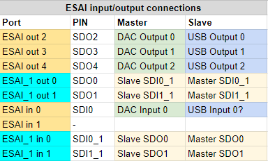
- Parts on the Master that have their output set to one of the analog outputs are sent to the DAC by ESAI. This behavior is identical to the previous Virus series A, B and C
- Parts on the Slave that have their output set to USB are sent to USB from ESAI directly. Similar to how the Master sends data to the analog outputs
- The second DSP audio interface ESAI_1 is used in a bidirectional way to transfer audio channels from one DSP to the other. Audio channels are transferred in the following cases:
- The Master outputs to one of the USB outputs
- The Slave outputs to one of the analog outputs
- The same bidirectional transfer is used for the inputs in the following cases:
- The Master needs to process the USB input
- The Slave needs to process the analog input
The ESAI audio interface has the following setup:
- 44.1 kHz or 48 kHz
- 2 channels per port
The ESAI_1 audio interface is set up in a different way:
- 88.2 kHz or 96 kHz
- 3 channels per port
The doubled data rate allows to transfer four ESAI ports on two ESAI_1 ports. However, the setup is not 2 channels but 3 channels, because:
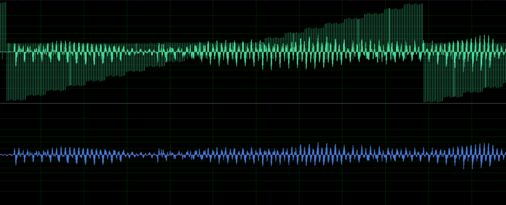
Additionally to the audio data, the third channel is used for real-time ring buffer synchronization between the two DSPs. Every audio processing cycle, the Master writes the 24-bit marker value $EDC987 at a fixed position ($b) in its ESAI_1 TX ring buffer. On the Slave side, the firmware reads the corresponding position in its ESAI_1 RX buffer and compares it against the expected marker:
- If the marker is found at the expected position: The two DSPs are in sync and audio data is extracted normally from the interleaved buffer.
- If the marker is NOT found (the ring buffer pointers have drifted): The Slave enters a resynchronization routine. It searches through the buffer in steps of
$10(one frame, 16 words) for up to 512 iterations to locate where the marker has drifted to. Once found, the drift offset is computed and the Slave adjusts its buffer read pointer (r7) to compensate. The Slave also writes the marker back at position$5as an acknowledgment to the Master.
This mechanism compensates for tiny timing differences between the two physically separate DSP clocks, which can cause their ring buffer read/write positions to drift over time.
In the emulator, this synchronization mechanism is not needed — both DSPs run in the same process and we synchronize them directly via buffering instead.
In a wave editor, the raw ESAI_1 stream looks like this (and sounds awful):
ESAI_1 Inter-DSP Link Specifications
| Parameter | Value |
|---|---|
| TX block size | 6 pins × 3 slots × 2 (double rate) = 36 words |
| RX block size | 4 pins × 3 slots × 2 (double rate) = 24 words |
| Sync marker | $EDC987 at TX position $b, search stride $10 |
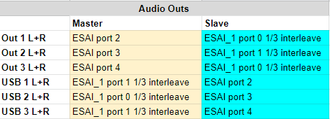
A summary where each selected output ends up on the audio bus can be found below:
Virus TI Snow
The Snow is a compact single-DSP variant of the TI:
- Uses 1× DSP56367 @ 163 MHz (overclocked from 150 MHz stock) with the same 1 MB memory configuration as the TI
- Limited to 4 multitimbral parts (vs. 16 on the full TI)
- 4 analog outputs (2× stereo), 6 USB outputs (3× stereo)
- Same ESAI audio interface, same preset format
- No inter-DSP link (ESAI_1 not used)
Reverse Engineering
Both the microcontroller code and the DSP code can be disassembled using your favourite disassembler (we are using IDA Pro). We also maintain a collection of complete DSP assembly dumps for all hardware variants (Virus A, B/C, Snow, TI, TI2).
Microcontroller
Just load the entire flash ROM into IDA and select Intel 8051 as the processor type (and select the correct device name, see the hardware list). The RESET_0 routine should be visible (which is the main entry point).
Note that some routines are not recognized automatically (such as the flash programming ones). You can go to the correct offset and press c to instruct IDA to disassemble those.
DSP Code
You can use the tools in this repository to extract the DSP program from any Access Virus flash dump file.
It performs the BootROM method described above to extract the DSP memory and write it to a file. Then load up IDA and select dsp563xx as the processor type.
The entry point can be determined by looking at command 4. For the Virus TI, the entry point is $D0C.
We stumbled upon an issue with the cross-references in IDA. With the jclr instruction for example, IDA seems to ignore the high bits of the destination address, causing a wrongly displayed x-ref. Fortunately, we have written our own disassembler that works correctly. Our disassembler is part of the DSP emulation repository.
Some helpful scripts and configuration files are available in the ida directory.
Keep in mind that IDA Pro loads dsp563xx binaries using little endian, while the DSP563 itself uses big endian byte order. We included a tool be2le.py to make conversion easy.
DSP Memory Patching
The emulator includes a ROM-version-specific memory patching system that applies fixes to certain DSP addresses after firmware loading. Patches are identified by MD5 checksum of the ROM file and may replace opcodes at specific addresses (using NOP $000000 or WAIT $000086) to work around timing-sensitive code or known firmware issues.